Decks may be defined for load attribution as well as composite beam design. Unbraced lengths for the top flanges of beams may also be controlled through the deck properties. Loads may be associated with the deck, or defined with the applied loads. Allowable span lengths can also be specified to avoid violating maximum span capabilities of the deck. Deck direction also controls the span of wood structural panels for flexible diaphragms.
Note
Diaphragm edges and openings must be defined to establish the extents of the deck. Properties for the deck are defined in the Deck General Properties Spreadsheet. A default deck is listed for each floor on the Floors Spreadsheet. However, local deck systems may be defined where deviation from the default deck system occurs.
For additional advice on this topic, please see the RISA Tips & Tricks webpage at risa.com/post/support. Type in Search keywords: Deck.
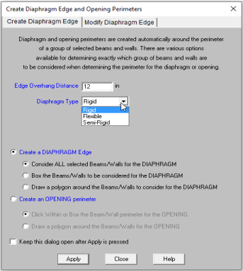
To create diaphragm edges or openings click ![]() on the Drawing Toolbar to open the Create Diaphragm Edge and Opening Perimeters dialog. Enter the edge overhang distance
and specify whether it is a diaphragm edge or opening. For diaphragm edges, select whether you want the area to be treated as a rigid or flexible diaphragm. For Diaphragm perimeter, select whether you want ALL selected Member/Walls to be
considered for the diaphragm perimeter or do you want to box or polygon the diaphragm perimeter, click Apply. For an opening, select whether
you want to click within or box the framed opening or draw a polygon
around the opening, click Apply. The new diaphragm edge or
opening will be shown on screen.
on the Drawing Toolbar to open the Create Diaphragm Edge and Opening Perimeters dialog. Enter the edge overhang distance
and specify whether it is a diaphragm edge or opening. For diaphragm edges, select whether you want the area to be treated as a rigid or flexible diaphragm. For Diaphragm perimeter, select whether you want ALL selected Member/Walls to be
considered for the diaphragm perimeter or do you want to box or polygon the diaphragm perimeter, click Apply. For an opening, select whether
you want to click within or box the framed opening or draw a polygon
around the opening, click Apply. The new diaphragm edge or
opening will be shown on screen.
To Create Diaphragm Edges or Openings
For Diaphragm Openings:
Note
The graphical Modify Edge tool lets you modify the diaphragm edges or openings that already exist in your model. You can redraw diaphragm edges, modify the overhang distance, modify edge intersections, delete an entire diaphragm edge or opening, or change the diaphragm type. You can modify diaphragm edges or openings one at a time by selecting the Click The Edges or Click Intersecting Points option and then click on the diaphragm edges or points you wish to modify. You may also modify multiple edges by selecting the diaphragm edges first and then using the Apply To ALL or Merge ALL option. See Graphic Selection for more on selecting.
To Modify diaphragm Edge and Openings
Note
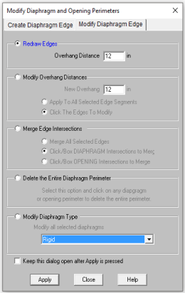
To Modify Diaphragm Type
The default diaphragm and deck properties and the deck angle are defined in the Floor Spreadsheet. If you have areas of your floor that are oriented differently or have different deck properties, you will have to assign new local deck properties to these areas.
To assign deck properties click ![]() on
the Drawing Toolbar to open the Deck Assignment dialog. Select
a Deck Type from the pull down list. See Deck
Properties - General for more information on Decks or to add
or remove decks from the list.
on
the Drawing Toolbar to open the Deck Assignment dialog. Select
a Deck Type from the pull down list. See Deck
Properties - General for more information on Decks or to add
or remove decks from the list.
Specify a Deck Direction by choosing Parallel to Horizontal, Parallel to Vertical or entering an angle that the span direction makes with the horizontal axis.
You may apply the deck properties by clicking within or boxing a deck area perimeter, by drawing a polygon around the deck area perimeter, or by drawing point to point.
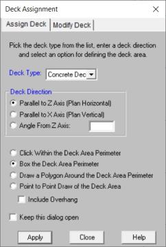
To Assign Deck Properties
Note
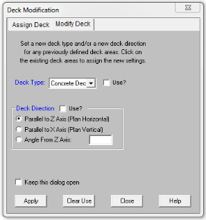
For existing decks that have been previously defined, you can use the Modify Decks dialog to make changes.
To modify deck properties click ![]() on
the Drawing Toolbar and click to the Modify Deck tab. Make your changes and make sure to check the Use? checkbox, as only selections with Use? checked will actually change in the model.
on
the Drawing Toolbar and click to the Modify Deck tab. Make your changes and make sure to check the Use? checkbox, as only selections with Use? checked will actually change in the model.
Note
The Deck Properties Spreadsheet records the deck properties and may be accessed by selecting Deck Properties on the Spreadsheets menu. The spreadsheet has two tabs: General, and Loads.
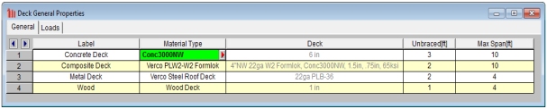
The General tab holds the general data for the decks. The Loads tab contains load information for the deck.
Define a new Deck
The entries for the General tab are explained below:
A unique label may be assigned to all of the decks manually or automatically. You can then refer to the deck by its label. You may relabel the deck at any time without affecting the application of the properties to the model.
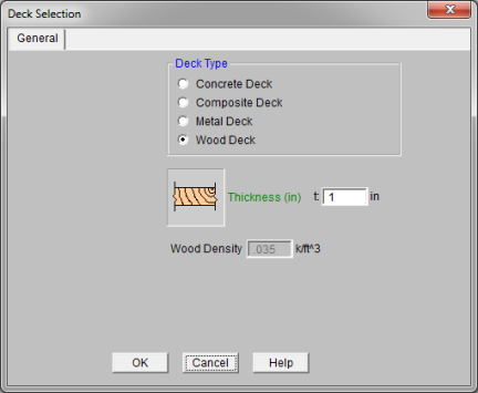
There are four material types available; Concrete Deck, Composite Deck, Metal Deck and Wood Deck. You can select the deck by clicking on the arrow ![]() . See Material Type for more information.
. See Material Type for more information.
This shows the selection from the Material Type dialogue. This is for display only, you cannot edit this directly. To change this information, you must go back to the Material Type dialogue.
The unbraced length that the deck provides to the top flange of the beams may be entered here. If left blank the deck is assumed not to brace the beam top flange and the unbraced length is determined from the spacing of the framing, the full length of the beam, and any values specified in the Beams spreadsheet. See Unbraced Lengths for more on how the unbraced length is determined.
Enter the maximum safe span allowed for the deck. If the span is exceeded, the location will be reported in the warning log.
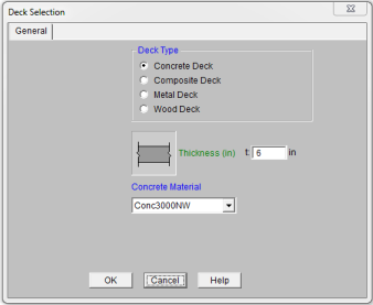
You enter the thickness and select the concrete material. The thickness is defined as the full thickness of a flat slab of concrete above the beams. The concrete material is a list from the Materials spreadsheet.
Note:
The decks are organized by Database/Manufacturer from the drop-down list, then you can select the deck.
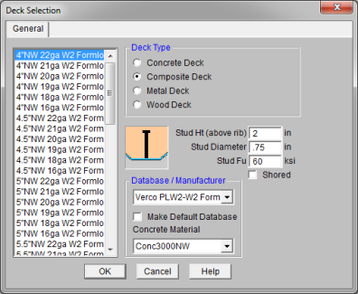
RISAFloor uses the deck properties for Composite Decks based on a database XML file in the "Decks" sub-directory of the RISA User Data folder. The location of this directory is based on the information of the Tools- Application Settings dialog. The program comes pre-loaded with XML files, each of which contains the required information for the composite beam design. The name of the XML file itself will be used in the list of the Database/Manufacturer.
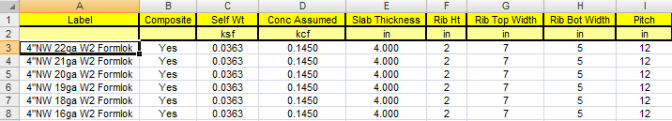
The Self Wt is from the XML database is used for the deck self weight, and you can confirm this in the Deck Loads tab of the Deck Definitions dialogue.
Note:
After selecting the deck, the corresponding Concrete Material must be selected. This list is the from the Materials spreadsheet. The weight of the concrete material will be checked to match the database value. The modulus of elasticity will be used to design composite beams, including the determination of the stud capacities.
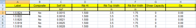
Rib Height defines the total height of the deck ribs. Enter 0 for a flat slab.
Rib Widths define the top and bottom widths of the rib. If the Rib Height is set to 0 the Rib Width values are ignored.
Rib Pitch defines the spacing of the ribs. If the Rib Height is set to 0 the Rib Pitch value is ignored.
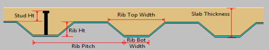
For the thicknesses given in the composite deck database, the thickness is defined as the total slab depth.
Stud Height defines the height of the shear stud above the rib to be used for composite beam design. There are a number of checks regarding stud height defined in the AISC.
Note
Stud Diameter defines the diameter of the shear stud.
Stud Fu defines the Ultimate Tensile Strength of the shear stud.
When the Shored box is unchecked, composite beams will be checked for pre-composite/construction loads using their bare beam section properties, and all other loads using their composite properties.
When the Shored box is checked, composite beams will be checked for all loads using their composite properties.
Note:
The decks are organized by Database/Manufacturer from the drop-down list, then you can select the deck to be used from the display window on the left side of the dialogue.
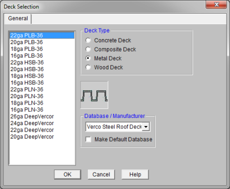
RISAFloor uses the deck properties for Metal Decks based on a database XML file in the "RISA_Decks" sub-directory of the RISA folder. The location of this directory is based on the information of the Tools- Application Settings dialog. The program comes pre-loaded with XML files, each of which contains the required information for the composite beam design. The name of the XML file itself will be used in the list of the Database/Manufacturer.
Note:
You enter the thickness of the wood deck. The self weight will be calculated based on the shown wood density. The density shown is not editable and is based on the first wood entry in the Materials spreadsheet under the Wood tab. You can change the density in the Material spreadsheet, or create a new wood material to change this value.
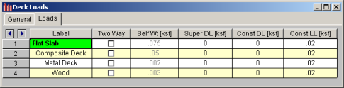
The Loads tab holds all the load data for the decks. See Load Types - Deck Loads or Loads - Vertical for more information on how loads are combined for solution.
The decks can be specified as one-way or two-way to control the attribution of the applied loads. Check this box if you want the area loads applied to the deck to be distributed based on two-way action. See Loads – Attribution for more information.
Self Weight is the weight of the deck system. This weight will be used as part of the pre-composite dead load (PreDL) and also as part of the post-composite dead load (DL) when creating load combinations for solution.
Note:
The Superimposed Dead Load (Super DL) is additional load that will be treated as additional deck self weight. This might be useful to account for deck topping or flooring materials that will be part of the dead load of the floor system. This load will be included for any calculations that include deck self weight (seismic mass, beam camber for hot-rolled steel and any places the refer to load categories DLPre and DL).
You may define construction dead load that occurs during construction but is not part of the final load on the system. This weight will be used as part of the pre-composite dead load (PreDL) but not included as part of the post-composite dead load (DL) in the load combinations for solution.
You may define construction live load that occurs during construction but is not part of the final load on the system. This weight will be used as part of the pre-composite live load (LLConst) but not included as part of the post-composite live load (LL) in the load combinations for solution.
Diaphragm edge perimeters must be specified to define the outer most extents of the floor deck or diaphragm if automatic load attribution or composite beam design is desired. The edge defines both the area available for loading and the available effective width for composite beams. While load and deck areas may be defined beyond the diaphragm edge, the portions outside the edge are ignored at solution time.
Diaphragm edges perimeters and openings can be generated automatically. See Creating Diaphragm Edges and Openings to learn how to draw and modify diaphragm edges and openings.
Diaphragm edges along with diaphragm openings may also be used to define rigid diaphragms for lateral analysis in RISA-3D. See RISAFloor & RISA-3D Interaction for more information.